- Tel: +86-15305875100
- E-mail: [email protected]
- Please contact us if you have questions.
CONTACT US


 English
 Español


Industry News
Nov 20,2026
How Does Electrical Noise Affect Panel Control Components
A conveyor stops for no clear reason. A pressure reading jumps while the process stays steady. A valve clicks twice when it should click once. Faults like these often trace back to electrical noise, not to a failed part. As drives, switching power supplies, and automated equipment crowd into the same cabinets, Panel Control Components share space and wiring with sources of interference. An Electric Solenoid Switch is a good example, because its coil is both a victim of noisy supply conditions and a source of switching transients.
Understanding Electrical Noise in Control Panels
Electrical noise means unwanted signals that disturb normal circuit operation. It moves through power cables, signal wiring, grounding connections, or electromagnetic fields. A modern cabinet holds PLCs, relays, contactors, sensors, power supplies, and drives within a small footprint, so a disturbance from one device easily reaches its neighbors.
Common Sources
- Variable frequency drives: Fast switching and long motor cables can introduce conducted and radiated interference.
- Switching power supplies: Rapid switching creates disturbances on supply and output lines.
- Motors and transformers: Magnetic fields can reach nearby control wiring.
- Relays and contactors: Opening and closing contacts produce transients.
- Solenoid coils: Interrupting an inductive load can create voltage spikes.
- Poor grounding: Weak bonding creates unwanted current paths.
Conducted and Radiated Paths
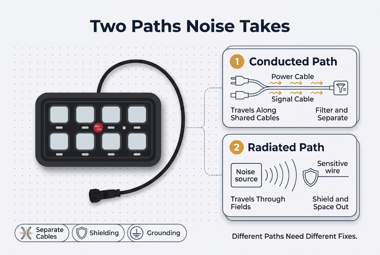
Conducted interference travels along shared supply lines and interconnected cables. Radiated interference travels through electromagnetic fields and is picked up by sensitive wiring or electronic modules placed near a source. The two paths call for different remedies, so a single filter rarely solves everything.
Effects on Different Components
The result depends on circuit sensitivity, construction, signal type, and the frequency and strength of the disturbance.
| Component | Possible Effect |
|---|---|
| PLC controllers | Incorrect inputs, unstable control signals |
| Sensors | Signal fluctuation, false detection |
| Relays | Unwanted switching responses |
| Contactors | Control circuit disturbances |
| Analog I/O modules | Measurement fluctuation |
| Communication modules | Data errors, dropped connections |
| Electric Solenoid Switch | Unstable coil operation, switching disturbance |
PLCs and I/O Modules
A controller reads electrical inputs to run its program. Noise on an input line may be read as a real signal, causing unexpected transitions or wrong responses. Analog inputs are especially exposed, since small variations alter readings from pressure, temperature, and flow transmitters. Input filtering, isolation, suitable wiring, and attention to electromagnetic compatibility help.
Sensors
Sensors often sit near motors and drives. Symptoms include inconsistent detection, proximity sensors switching unexpectedly, fluctuating analog values, and intermittent feedback. Choose sensors with suitable EMC characteristics and follow the maker's wiring guidance.
Relays and Contactors
When a coil is de-energized, its collapsing magnetic field creates a voltage transient that can disturb nearby electronics or the control supply. Coil suppression, wiring separation, and circuit protection limit the effect.
Communication Modules and HMIs
Data exchange depends on clean signals. Interference causes transmission errors and unstable links. Shielded cable, correct grounding, good connectors, and separation from power wiring all matter.
The Electric Solenoid Switch Under Noise
An Electric Solenoid Switch uses a coil to produce a magnetic field that moves a plunger or switching mechanism. Because the coil is inductive, switching it creates transients that can reach the control circuit and its neighbors.
Several conditions influence performance:
- Unstable coil voltage: Supply disturbances change the magnetic force, which can cause inconsistent actuation or an incomplete stroke.
- Inductive transients: Interrupting the coil releases stored energy as a voltage spike that can upset connected electronics.
- Electromagnetic coupling: The coil's field can induce unwanted signals in nearby sensitive wiring when routing is careless.
- Repeated switching: Frequent operation creates recurring transients whose effect depends on the load and suppression.
| Protection Method | Use |
|---|---|
| Flyback diode | Suppresses transients in suitable DC coil circuits |
| RC snubber | Reduces switching transients in suitable AC or DC circuits |
| MOV suppressor | Limits transient voltage across inductive loads |
| Separate control supply | Reduces interaction with sensitive circuits |
| Cable separation | Limits coupling between coil and signal wiring |
Match the method to the coil type, voltage, and the maker's recommendations. A flyback diode, for example, slows coil release, so check the required switching response first.
Component Selection
Protection starts before the panel is built. Look beyond rated voltage and current to these points:
- EMC specifications
- Insulation and isolation requirements
- Signal type and input sensitivity
- Switching frequency and load characteristics
- Temperature and humidity
- Manufacturer installation and suppression recommendations
Fit the specification to the real environment. A cabinet with drives and motor switching needs careful cable separation and grounding, while a panel handling low-level analog signals needs more attention to isolation and shielding. For PLCs and I/O modules, review noise immunity and input filtering. For relays, contactors, and any Electric Solenoid Switch, review coil characteristics and suitable suppression.
Installation Practices
Correct parts can still fail when wiring and grounding are poor.
Separate Power and Signal Wiring
Motor cables from drives radiate strongly, and running them beside sensor or communication cables increases coupling. Good habits include:
- Separate ducts for power and sensitive signals
- No long parallel runs between motor outputs and analog lines
- Crossing cable groups at right angles when separation is impossible
- Following the equipment maker's separation guidance
- Keeping communication wiring away from switching devices and coils
Shielding and Grounding
Shielded cable reduces coupling only when it is terminated properly. Bonding quality and frequency range affect results. Use shielded cable for analog and communication circuits, keep bonds low in impedance, connect conductive panel structures well, and treat protective earth and functional grounding separately. Follow the EMC instructions of the equipment rather than one universal rule.
Panel Layout
Place drives and motor switching gear in a power section. Keep PLCs and signal modules away from major sources. Arrange relay and contactor circuits to limit wire crossings, and leave room for cable routing and grounding. A tidy layout also makes inspection and maintenance easier.
Circuit-Level Design
External protection should not carry the whole burden.
Grounding gives fault currents a path, while bonding and functional grounding help control interference. Poor connections between enclosures, mounting plates, and conductors disturb the intended current paths, so design them to the applicable standards.
Filters and suppression devices help when chosen and fitted correctly. Options include EMI filters on supply circuits, transient suppression for inductive loads, input filters, isolation between different references, and coil suppressors for relays and solenoids. Selection should consider noise frequency, load current, voltage, and installation conditions. A wrong filter may add voltage drop, alter switching behavior, or miss the real interference path.
Signal integrity depends on the full path from sensor output through cable and input module to ground. Differential transmission, isolation, controlled return paths, and suitable cable selection all reduce interference, and the wiring method must suit the signal type.
Troubleshooting Noise
Treat noise as one suspect among electrical and mechanical faults. Start by noting when the problem appears: during motor starts or stops, drive speed changes, relay or contactor switching, activation of an Electric Solenoid Switch or solenoid valve, or power supply operation. A link between a switching event and an odd response narrows the source.
Then inspect the cabinet for loose terminals, damaged insulation, poorly routed signal cables, weak shield terminations, and grounding faults. Check whether high-power and sensitive wiring share paths.
Finally, use suitable instruments to look at supply disturbances, transients, and signal stability. Verify the condition of filters and coil suppressors, and compare behavior under controlled conditions to confirm that the protection addresses the actual path.
Building Reliable Panels
Noise protection depends on component quality, circuit design, installation, and the operating environment working together. System integrators and panel builders should choose compatible Panel Control Components and review coil specifications, electrical ratings, switching needs, installation conditions, and suppression for every Electric Solenoid Switch. Teams planning a new cabinet or replacing a switching part can contact us to discuss component requirements, operating conditions, and product selection.
Related Products
Looking For Business Opportunity?
Request for a call today

No.128, Qianjin Road, Qianfeng Industrial Zone, Tangxia Town, Ruian, Zhejiang, China
-
-
Sophia Ye
-
Phone: +86-15305875100
-
WhatsApp: 15305875100
-
Email: [email protected]
-
- Mobile Terminal
Copyright 2024 Zhejiang Xiangrui Auto Electric Co., Ltd.

Relays And Modified Parts Factory
