- Tel: +86-15305875100
- E-mail: [email protected]
- Please contact us if you have questions.
CONTACT US


 English
 Español


Industry News
Oct 23,2026
How Do Panel Control Components Improve Fault Diagnosis
When a machine stops unexpectedly, the time needed to find the cause often depends on how its control cabinet is arranged. A technician may need to trace a signal, check a connection, inspect a switching device, or confirm that a controller receives the expected input. Crowded components and hard-to-read labels turn a simple inspection into a long task.
Well-organized Panel Control Components give each device a clear place and purpose. Functional zones, consistent labels, readable diagrams, accessible test points, and enough maintenance space help a technician understand the cabinet before troubleshooting begins. The layout should let people follow the path from a control command to the device that carries it out, with room to inspect connections and replace parts.
How Should Components Be Zoned?
Why Does Grouping Matter for Diagnostics?
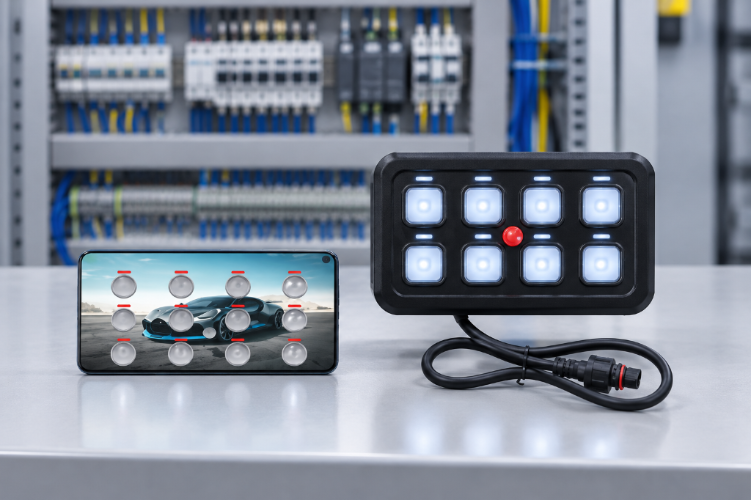
A cabinet brings together power distribution, switching, signal processing, protection, and machine control. These devices form a connected system, so a fault in one area can show up elsewhere. A technician should be able to identify each component and its relationships without guessing where a wire leads.
| Component Group | Organizational Purpose |
|---|---|
| Power distribution | Keeps supply devices easy to identify |
| Control devices | Groups equipment that manages machine operation |
| Signal interfaces | Makes incoming and outgoing signals easier to trace |
| Switching devices | Helps locate components that control electrical loads |
| Protection devices | Supports inspection of circuits and protective elements |
| Terminal blocks | Gives field wiring a clear connection point |
Devices should not be grouped only because they look alike. Electrical function, operating conditions, wiring paths, and service needs all count.
What Should a Zoning Plan Consider?
Zoning gives the cabinet an internal structure, in place of fitting devices wherever a gap remains. If a machine ignores an input, the technician can follow the documented path from the input terminal to the control device and then to the output circuit. Zones should also reflect how technicians work, placing devices checked together near one another when electrical separation and heat management allow.
- The function of each component
- Relationships between connected devices
- Direction of incoming and outgoing wiring
- Need for electrical separation
- Space for inspection and replacement
- Location of parts needing frequent attention
Space efficiency still matters, but it should not hide important components.
How Do Labels and Diagrams Help?
Which Identification Items Are Useful?
Labels link physical parts to drawings and maintenance records. Without a consistent system, a technician may open several similar devices before finding the one named in a service note. Component identifiers, terminal markings, and wire labels should follow the same naming logic, so people can move between cabinet and diagram without translating.
| Identification Item | What It Clarifies |
|---|---|
| Component label | Names the device in the cabinet |
| Wire label | Shows which conductor is being inspected |
| Terminal marking | Connects a wire to its termination point |
| Zone label | Indicates the functional area |
| Drawing reference | Links the part to its documentation |
Labels must stay readable after installation and sit where they can be seen without moving cables or removing other devices. They should be updated whenever a device is replaced or a circuit changes.
How Should Diagrams Match the Cabinet?
A wiring diagram helps only when it reflects the installed cabinet and not an earlier design. It should use the same identifiers and terminal names found on the equipment. A layout drawing shows where parts are mounted, a circuit diagram explains connections, and terminal plans cover field wiring and cable routing.
These documents should agree with each other. If a device has one name in the layout drawing and another in the circuit diagram, a technician loses time confirming they describe the same part. Changes made during commissioning, repair, or upgrades belong in the service record so the next technician works from an accurate description.
Where Should Test Points and Switching Devices Go?
What Makes Test Access Useful?
Test points let technicians check a circuit without dismantling large parts of the cabinet. Plan them around the checks likely during commissioning and maintenance, such as confirming a supply, observing a control signal, or seeing whether a switching device receives its command. They must be clearly marked and reachable with suitable test equipment. Reaching one should never require unsafe contact with nearby live parts.
How Should Switching Devices Be Arranged?
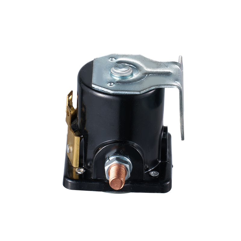
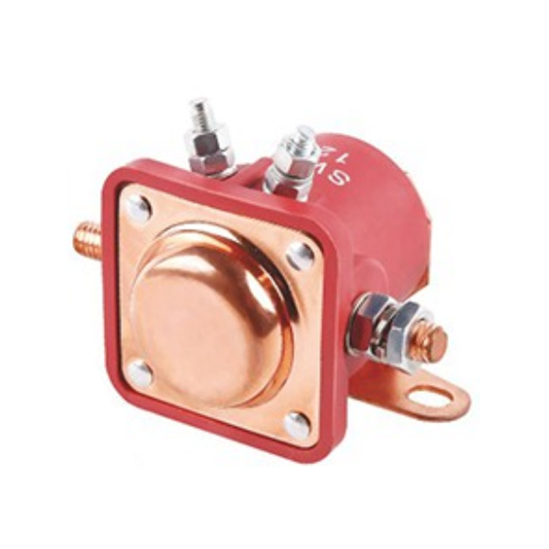
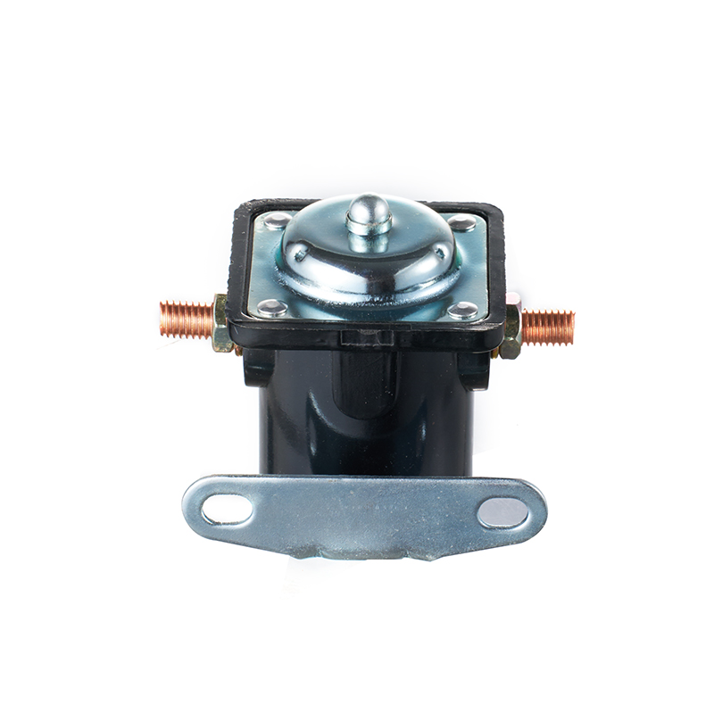
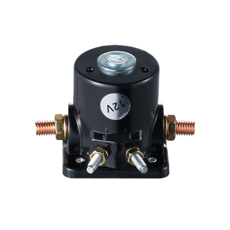
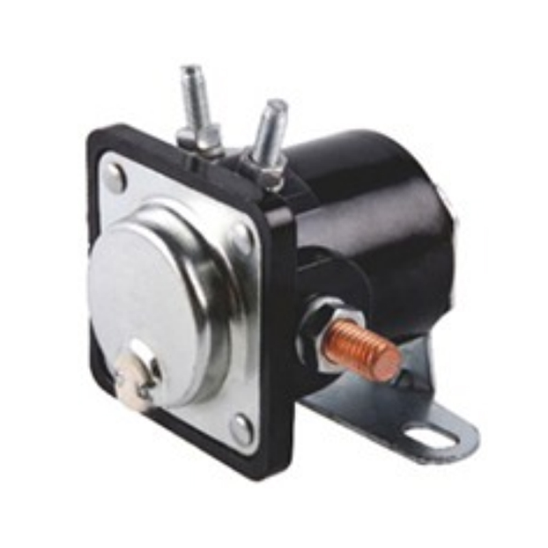
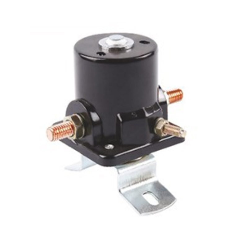
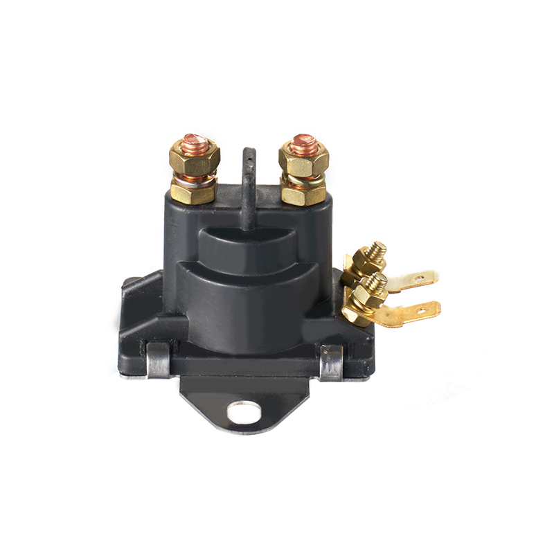
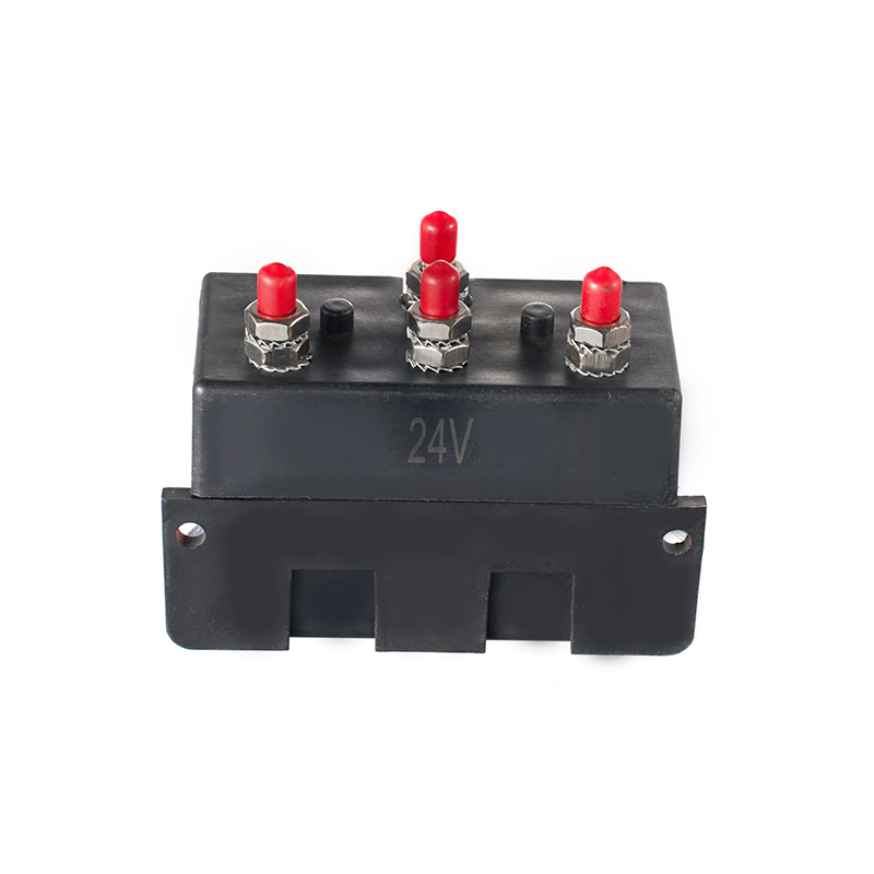
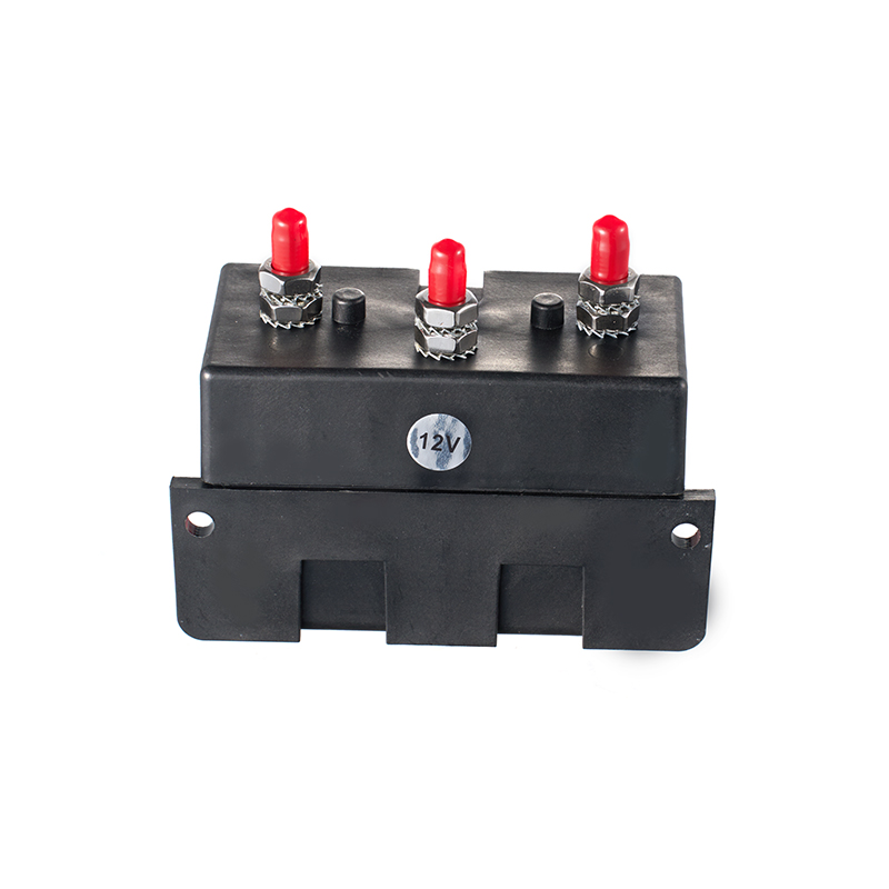
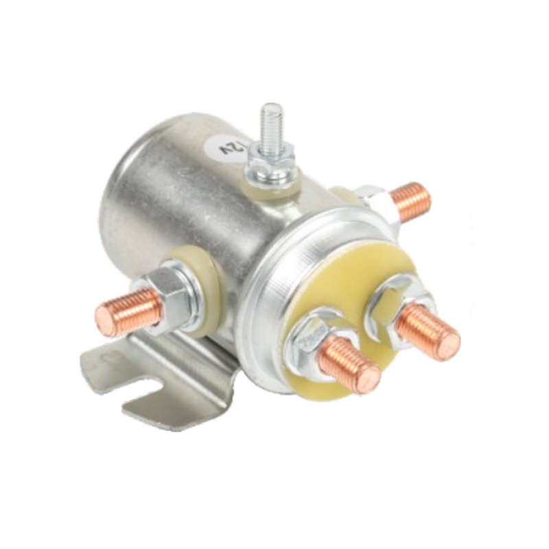
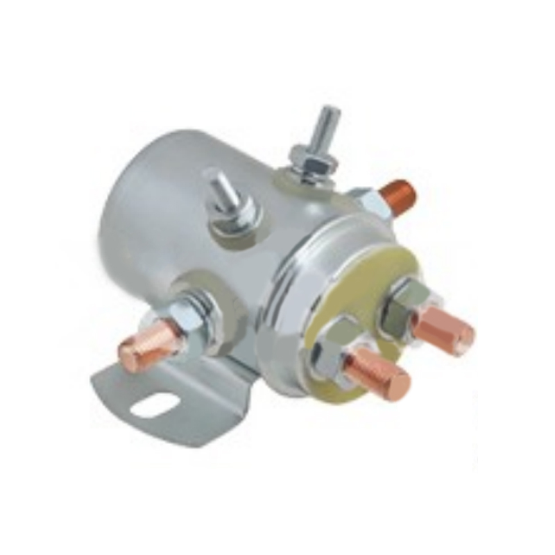
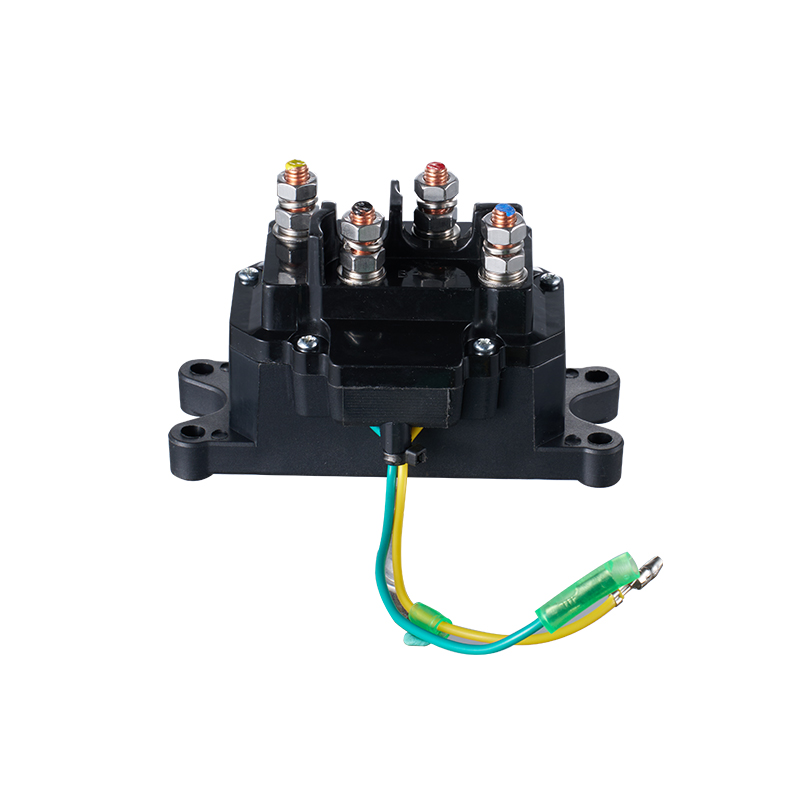
An Electric Solenoid Switch may sit in a control circuit that triggers a mechanical or fluid-related function. When its operation is in doubt, the layout should help the technician identify the device, find its control connections, and follow the signal path in the documentation. Where the design includes them, supply, control input, output connections, and protection should be easy to identify around it.
Diagnosis should separate a missing command from a device that receives a command and fails to respond. A clear layout allows checks in sequence, so a part is not replaced on the strength of visible machine behavior alone.
Grouping related devices makes signal tracing more direct, but it must not override electrical separation, heat control, or safe access. Devices with different operating conditions may need distance even when they share a sequence. If sensors or outputs may be added later, leave a route for new devices and wiring.
How Do Wiring Routes and Upkeep Keep the Cabinet Readable?
Why Do Routes and Space Matter?
Cables that cross at random between groups hide labels, block terminals, and make tracing difficult. Ducts and defined routing paths keep conductors grouped by function and let technicians follow a wire without pulling apart unrelated bundles.
Maintenance space matters equally. A technician may need to remove a component, operate a terminal, connect a tester, or inspect a mounting point. A cabinet packed too tightly forces extra dismantling and raises the chance of disturbing nearby connections. Designers should consider how a device will be removed, not only how it is installed, since adjacent wiring, duct covers, or structure can block access.
What Routine Keeps It Diagnosable?
A well-designed cabinet becomes hard to read if its organization slips. Labels fade, changes go unrecorded, and replacement parts get fitted in ways that ignore the original layout. After an approved change, the responsible team should confirm that labels, wire markings, diagrams, and records match the installed arrangement.
Follow the manufacturer's instructions and applicable safety procedures. Cabinets can contain hazardous energy, so only authorized personnel should work on circuits, using the required isolation and verification practices.
- Check that labels remain readable
- Confirm identifiers match the drawings
- Look for loose or damaged wiring where inspection is permitted
- Keep cable routes and service access clear
- Record approved changes
- Review whether recurring faults point to a layout or documentation issue
For equipment builders and integrators, diagnostic access belongs alongside component selection, electrical design, installation, and service planning. Clear zones, consistent identification, accurate diagrams, reachable test points, and practical maintenance space let technicians trace faults with less disruption.
Related Products
Looking For Business Opportunity?
Request for a call today

No.128, Qianjin Road, Qianfeng Industrial Zone, Tangxia Town, Ruian, Zhejiang, China
-
-
Sophia Ye
-
Phone: +86-15305875100
-
WhatsApp: 15305875100
-
Email: [email protected]
-
- Mobile Terminal
Copyright 2024 Zhejiang Xiangrui Auto Electric Co., Ltd.

Relays And Modified Parts Factory
