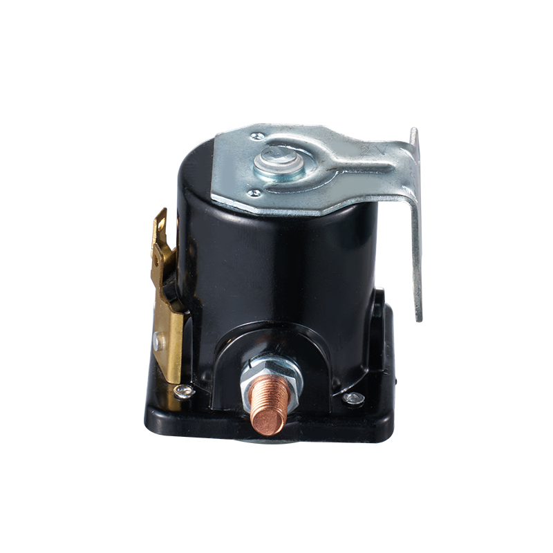
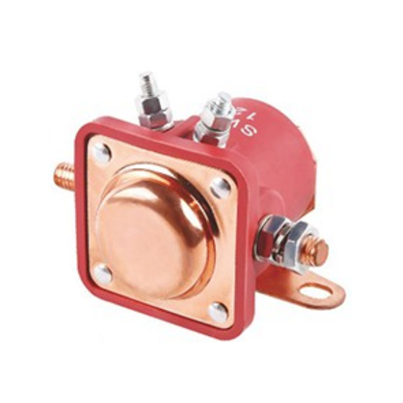
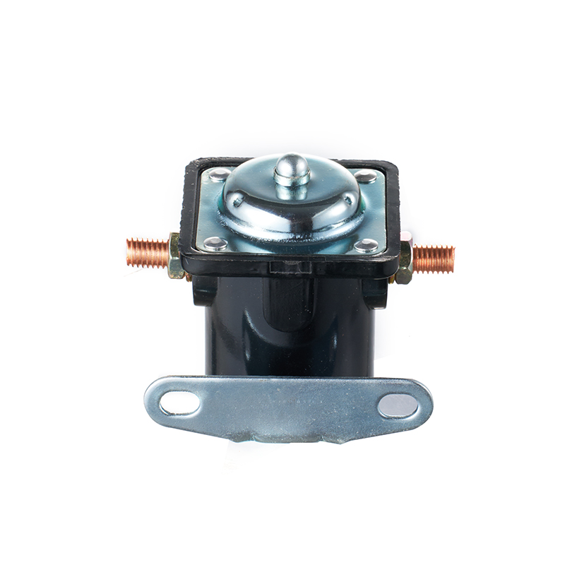
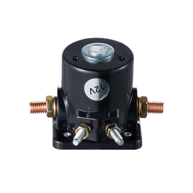
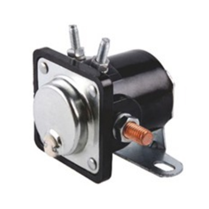
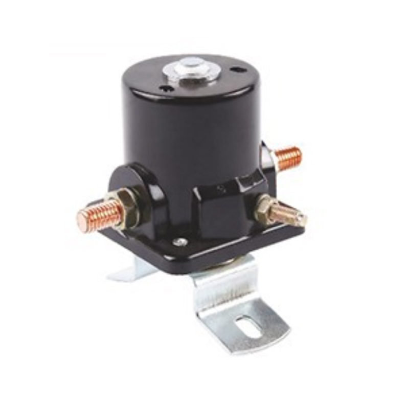
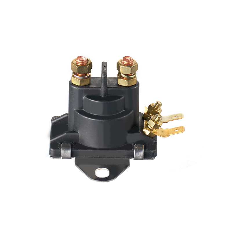
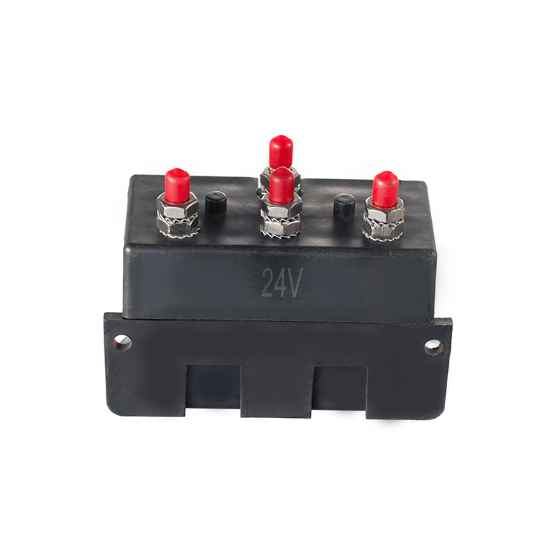
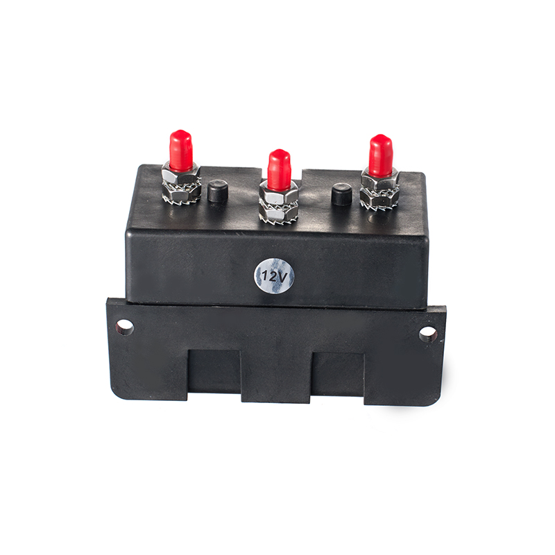
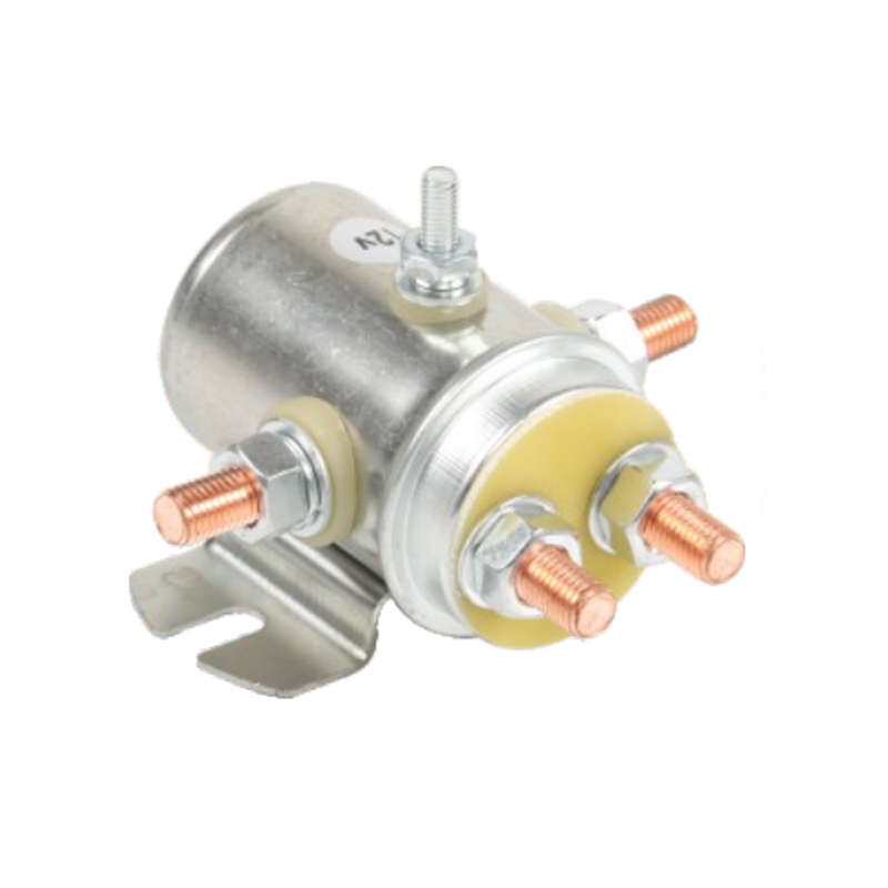
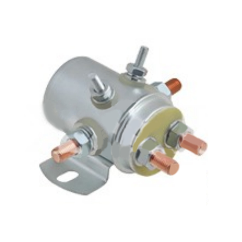
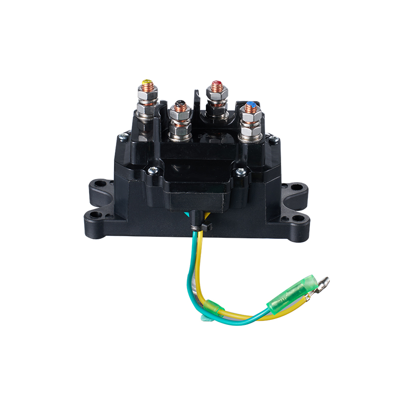
A machine can be running normally one moment and need direct attention the next. A pump may follow automatic pressure settings during production, but when a technician needs to inspect a valve or check a motor, local control becomes necessary. This is where Panel Control Components make a difference. They help manage commands from operators and automatic systems, while an Electric Solenoid Switch can activate a valve or another connected device when the circuit sends the right signal. The challenge is making these functions work together without allowing different commands to interfere with each other.
In a busy production facility, operators cannot always rely on a machine to follow its usual sequence. Equipment needs to be checked, adjusted, and sometimes stopped for maintenance. Manual and automatic modes provide different ways to handle these situations, but the change between them needs to be clear at the electrical level.
Think about a water pump supplying a production line. During normal operation, the pump starts when pressure falls and stops when the required pressure returns. The control system handles these actions without requiring someone to stand beside the panel.
The situation changes when the pump needs inspection. A technician may want to test the motor, check a connection, or see whether a valve responds correctly. Manual mode makes these tasks easier because the operator can issue a local command rather than waiting for the automatic process.
Automatic mode is more suitable for regular production. It allows equipment to respond to sensor signals and programmed conditions, which is useful when several machines need to work together.
| Operating feature | Manual Mode | Automatic Mode |
|---|---|---|
| Command source | Operator | Control system |
| Main input | Push buttons and switches | Sensors and programmed signals |
| Typical use | Testing and maintenance | Routine production |
| Equipment response | Follows permitted local commands | Follows programmed conditions |
| Operator involvement | Direct control | Monitoring and intervention |
Both modes may use the same motor, pump, or valve. What changes is the source of the command and the electrical path through which it reaches the equipment.
A control cabinet contains several devices that may look similar to someone unfamiliar with electrical systems. Their jobs, however, are quite different.
A selector switch handles mode selection. A PLC processes control instructions. Relays and contactors manage electrical switching, while solenoid devices activate their connected mechanisms.
A Manual-Off-Auto selector switch gives the operator a direct way to choose the machine's operating mode.
When the switch moves to Manual, the designated local control path becomes available. Selecting Auto enables the automatic command path. Some panels also include an Off position that prevents normal operating commands.
One detail is easy to overlook: the selector switch does not necessarily start the motor or move the valve. Its contacts change the control circuit so that the selected command source can be used.
In automatic mode, a PLC receives information from sensors and checks it against the programmed conditions.
For example, a level sensor may indicate that a tank needs filling. The controller checks whether the pump is available and whether the required operating conditions are met. If everything is in order, it sends an output signal.
A PLC may also monitor alarms, motor status, and valve positions. Depending on the design, some of these monitoring functions continue when the equipment is in Manual mode.
Relays are used to switch control signals between circuit sections. Contactors are commonly used when a motor or another electrical load needs to be connected to its power supply.
A typical arrangement may involve a PLC output operating a relay, which then energizes a contactor coil. The contactor's main contacts control the motor supply.
This separation matters. A small control signal should not be expected to handle the power requirements of an industrial motor.
An Electric Solenoid Switch uses an electromagnetic coil to create movement or change a switching state, depending on the device design.
In a fluid handling system, a solenoid-operated valve may open or close when its coil receives the correct electrical signal. Other solenoid devices can operate release mechanisms or switching assemblies.
It is worth keeping the functions separate. A selector switch chooses Manual or Auto. A solenoid device performs its assigned switching or movement task after receiving an authorized command.
Consider a pump that needs to be checked before normal production begins.
The technician turns the selector to Manual and presses Start. The control circuit checks the required conditions, then allows the command to reach the motor control circuit. A relay may switch the signal, and a contactor controls the power supplied to the motor.
If the pump is connected to an electrically operated valve, another control output may energize the solenoid coil. The technician can then observe whether the valve moves and whether the pump behaves as expected.
Sometimes the motor starts, but the valve does not respond. That is a useful reminder that sending a command and completing an action are two different things. The problem may involve the coil supply, wiring, valve mechanism, or another part of the circuit.
Manual mode is also useful for checking individual equipment functions that normally form part of a longer automatic sequence. However, direct operation must still follow the machine's safety requirements. Emergency stops, overload protection, and required interlocks should remain active.
Automatic operation is not simply a timer switching equipment on and off. It often involves several inputs and conditions that need to be checked together.
A pressure sensor may detect a change in a pipeline. A level sensor can indicate that a tank is nearly empty. The PLC receives these signals and decides whether the pump should run.
The same system may also control an electrically operated valve. When the controller sends the relevant output, the Electric Solenoid Switch energizes its coil and activates the connected mechanism.
In a larger installation, the order of operation matters. A valve may need to reach a certain position before the pump starts. Another machine may need confirmation that the previous operation has finished.
This is where equipment feedback becomes useful. A limit switch or position sensor can tell the controller whether the requested movement has actually taken place. Without feedback, the system may only know that a command was sent, not whether the equipment responded.
The actual challenge often appears when a machine is already running.
Imagine a pump operating under manual control. The operator moves the selector switch to Auto. Should the PLC immediately start its automatic sequence? Not necessarily. The controller may need to check the current motor status, valve position, and process conditions before accepting another command.
The selector switch changes the available control path. The PLC and associated electrical devices determine how the equipment should respond.
| Component | Function during a mode change |
|---|---|
| Selector switch | Identifies the selected mode |
| PLC | Checks conditions and processes commands |
| Relay | Switches or connects control signals |
| Contactor | Controls the motor power circuit |
| Electric Solenoid Switch | Activates its assigned mechanism |
| Sensors | Report actual equipment conditions |
There is also the question of what happens to an existing command. Some machines require a controlled stop before another mode becomes active. Others require a fresh start request after switching.
The correct arrangement depends on the machine's electrical design. It should not be left to guesswork.
Imagine a liquid transfer system with a motor-driven pump and a solenoid-operated valve.
During normal production, the PLC monitors process conditions and sends commands to the pump and valve circuits. When the valve needs to open, the solenoid coil receives its electrical supply and moves the valve mechanism.
Later, a technician needs to inspect the valve. Manual mode allows local operation without waiting for the normal production sequence.
Once the inspection is finished, the valve position and pump status need to be checked before automatic operation resumes. If the valve is still in an unexpected position, the automatic sequence may not be ready to continue.
This is particularly important in connected factories. A monitoring screen may show that a command was issued, but that does not prove that the motor has started or the valve has reached its required position.
A mode switching problem does not always come from the selector switch. A loose terminal, worn relay contact, damaged cable, or faulty solenoid coil can affect the whole control process.
During an inspection, technicians should pay attention to the actual machine condition.
Panel indicators can also be misleading when their functions are not clearly defined. A light showing that an output has been activated does not necessarily confirm that the equipment has completed the requested action.
Electrical checks should be performed by qualified personnel using suitable isolation procedures and the manufacturer's instructions.
The selection process should start with the machine, not the product catalogue. A selector switch needs the right contact arrangement, while relays and contactors must match the electrical requirements of the connected circuits.
An Electric Solenoid Switch also needs to suit its intended use.
| Selection factor | What to check |
|---|---|
| Coil voltage | Compatibility with the control supply |
| Current rating | Suitability for the circuit |
| Switching function | Required movement or switching action |
| Duty cycle | Expected operating frequency |
| Installation environment | Temperature, moisture, and dust |
| Mounting arrangement | Compatibility with the equipment |
For solenoid-operated valves, fluid type, working pressure, flow direction, and valve construction also affect the selection.
Maintenance access deserves attention during panel design. Technicians need to identify devices, trace wires, inspect terminals, and find circuit information without unnecessary difficulty.
Remote monitoring adds another consideration. Connected systems can make equipment conditions easier to view, but seeing a machine's status is not the same as having permission to change its operating state. Local controls, automatic sequences, and remote commands should have clearly defined permissions.
When reviewing a control panel, it helps to look beyond individual product specifications. The selector switch, PLC, relays, contactors, and Electric Solenoid Switch all need to respond correctly as part of the same operating circuit. Their connection and control logic determine what happens when an operator takes over from the automatic sequence, or when a machine returns to normal production.
Request for a call today